
Coverlay PCB for Military Applications
Coverlay PCB for Military
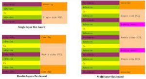
A coverlay pcb is an essential component for a flexible circuit board. It insulates copper traces and protects the board from corrosion, in much the same way as a solder mask on a rigid PCB. In addition, coverlay helps ensure that assembly paste, adhesives and other materials adhere properly to the flex board. It can also reduce stress on the flex board and extend its life.
There are several types of coverlay material available for flex PCBs, but polyimide is generally preferred for its excellent thermal stability and durability. This film is thicker than other coverlay options, and can withstand soldering temperatures of up to 400 degrees Celsius without degrading. In addition, polyimide is highly resistant to acids and bases, making it a good choice for harsh environments.
When coverlay is used on a flexible printed circuit board, it must be properly applied and cured to avoid defects such as wrinkles, bubbles and delamination. These flaws can result in cracking of the coverlay and open circuits. During the lamination process, careful temperature control and vacuum pressure are critical to prevent wrinkles and bubbles from forming. Wrinkles can also affect the adhesion of the flex circuit board to the substrate, leading to delamination or loss of dielectric properties.
Another issue with flexible Printed circuit boards is the concentration of stress in certain areas of the substrate. This can cause cracking of the flex board, particularly near the edges. This can be overcome by designing the flex circuit board to minimize stress in these areas through proper component placement, grounding and isolation techniques.
Coverlay PCB for Military Applications
The high power generated by many military systems creates significant heat that must be dissipated to maintain system performance and longevity. Proper design techniques can help disperse this heat through the use of thermal compounds, large copper planes and conductive paths, and larger pad sizes. This can also improve the lifespan of the flex circuit board by decreasing thermal fatigue.
Other considerations for a flex PCB include the selection of materials and thicknesses for both the bare copper and the coverlay. Rolled annealed copper is preferable for fatigue resistance compared to electro-deposited copper. It also has a lower porosity, which reduces the risk of oxidation and galvanic corrosion. Flex PCBs should also be designed with an expanded copper foil strain window to maximize flex life.
A stiffener can be added to a flex PCB to add support for surface mount components. Stiffeners are typically made of kapton or FR4 and attached with thermally cured adhesives. They can be routed, laser cut, or punch and die set. The thickness of the stiffener depends on the shape, size and complexity of the components. A bared flex circuit should overlap the stiffener by 0.030″ to relieve stress and protect it from damage during assembly.
A flex PCB can have a variety of openings for components, test points and other features. These openings must be accurately sized to ensure the correct operation of the flex circuit board. To do this, a CO2 laser can be used to ablate the desired openings in the flex circuit board’s underlying polyimide or polyester coverlay layer. Mechanical routing can be used as an alternative, but it lacks the accuracy of a laser system.