
How to Troubleshoot Electronic Circuit Boards
Troubleshoot Electronic Circuit Boards
Electronic circuit boards (PCBs) are complex and sometimes elusive. Using a variety of tools and techniques, you can troubleshoot a PCB with the goal of finding the cause of the problem, whether it’s a broken connector or a missing component. To begin, look for visible signs of damage to the board. These include burnt components, cracked ICs, and shorted traces. You can also use your sense of smell, as some blown capacitors give off an acrid odor.
In addition, physical inspection can be helpful to identify problems that aren’t immediately apparent. Checking for loose connections and solder bridges is important, as they can lead to short circuits of signal and power lines. You can often find these with a high-power microscope, which is an essential tool for PCB mapping and troubleshooting. It is also helpful to have a second, functional electronic circuit boards available for comparisons and visual inspections.
A basic method of troubleshooting is to test each component individually on the PCB, using a multimeter or LCR meter. This is one of the most effective ways to identify problems in individual components like resistors, capacitors, diodes, MOSFETs, LEDs, and switches. The individual component values should register less than or equal to their stated value, and if they don’t, that’s an indication of a problem.
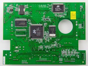
How to Troubleshoot Electronic Circuit Boards
Another effective technique is to conduct a hFE test with the multimeter, which checks the gain and forward voltage of transistors. You can do this by connecting the multimeter’s probes to the transistor base, emitter, and collector pins. If the transistor is good, you should see a 0.6V forward drop between these points. Alternatively, you can also do a simple continuity test by touching a probe to the foil and another to a copper trace on the PCB. If the multimeter beeps, it means that there is a connection between the two points.
It’s essential to make sure that the multimeter’s range and function settings are correct before conducting a test. This will prevent accidental overvoltage, which can damage the circuit board and potentially hurt you. You should also wear protective gear, such as gloves and goggles, during the testing process.
To test integrated circuits, you can use a logic analyzer or oscilloscope. The former is ideal for digital logic circuits, while the latter works best for analog circuits. The simplest way to diagnose an integrated circuit is to compare it to another one of the same type. This will help you identify any errors in the programmable logic, such as a bad clock, memory, or peripheral interface. It’s also a good idea to read the datasheet of the integrated circuit before performing any tests. This will provide you with information about test procedures, min gain ratios, and max current ratings. Having this information can help you troubleshoot the problem faster and more effectively.